Wall framing relies on continuity to properly transfer loads from the roof and floors down to the foundation. One common framing deficiency observed during inspection is a top plate splice occurring between studs without proper staggering or approved tying.
Although the wall may appear structurally complete, an unsupported or improperly aligned splice interrupts the load path and does not comply with the Ontario Building Code.
When identified in a loadbearing wall, this condition typically results in a failed framing inspection.
Field Example — Unsupported Top Plate Splice
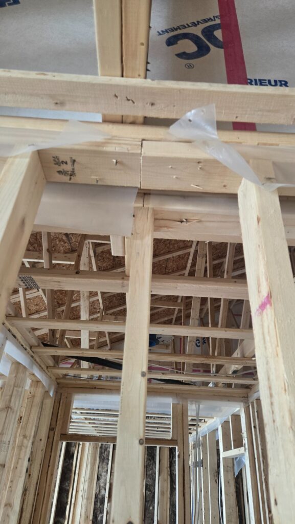
Field example showing a top plate joint occurring mid-wall between studs without proper staggering or support.
In this example, the top plate joint occurs directly between studs and is not staggered from the adjacent plate. The splice is not supported over a stud and no approved steel tie plate is installed.
Although the plates are fastened together, this configuration does not meet the structural intent of the Code for loadbearing walls.
Proper Configuration — Staggered Top Plate Joints
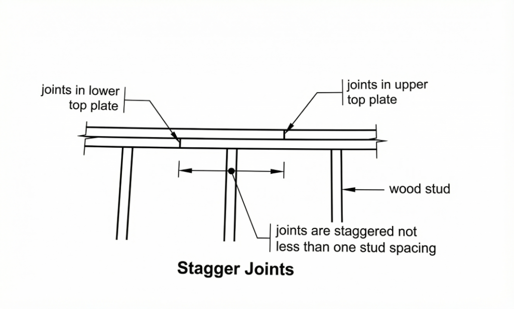
Double top plate joints must be staggered at least one stud spacing to maintain structural continuity.
Why Proper Top Plate Splicing Is Required
OBC 9.23.11.4.(1) — Joints in Top Plates
Plain-language requirement:
Joints in the top plates of loadbearing walls must be staggered at least one stud spacing.
The purpose of this requirement is to:
- Maintain structural continuity
- Ensure proper distribution of vertical loads
- Prevent a single weak plane across the wall
- Preserve the integrity of the load path
If both top plates break at the same location, the wall loses structural redundancy at that point and creates a potential failure plane.
WhWhy This Condition Is a Problem
When a splice occurs mid-wall without proper staggering or tying:
- Structural continuity is reduced
- Loads may not transfer efficiently across the joint
- Concentrated stresses develop at the splice location
- The wall becomes vulnerable under roof or floor loading
Even though the framing may feel rigid during construction, the structural weakness becomes critical once the building is fully loaded.
For this reason, inspectors routinely verify top plate continuity during framing inspections.
Typical Correction Strategies
Correction depends on the framing configuration but commonly includes:
- Installing a full-height stud directly under the splice to provide proper vertical support
- Staggering the joint a minimum of one stud spacing
- Relocating the splice directly over a stud
All corrective work must restore proper load transfer and structural continuity in accordance with OBC 9.23.11.4.
What Inspectors Commonly Verify
During framing inspection, verification typically includes:
- Splices not aligned in double top plates
- Minimum one stud spacing stagger
- Proper lapping at corners and wall intersections
- Continuous load path through the wall assembly
Correcting these details early avoids re-inspection delays and unnecessary site disruption.
Key Takeaway
Top plate splices in loadbearing walls must maintain structural continuity.
A mid-wall splice occurring between studs without proper staggering or support does not comply with OBC 9.23.11.4 and will typically result in a framing deficiency.
Providing proper support — most commonly by installing a stud directly beneath the splice or staggering the joint — restores the load path and avoids re-inspection delays.
Code Reference
OBC 9.23.11.4. — Joints in Top Plates
Disclaimer
Disclaimer: This article is for general educational purposes only. Building Code interpretation and enforcement may vary by municipality. Always confirm requirements with your local Authority Having